T172
T172 GMAW OAW is an iron based steel alloy with a near nanoscale (submicron) microstructure that features extreme abrasion resistance with high toughness, high volume of hard phases and superior high temperature hardness. T172 is an alternative to chrome and tungsten carbides.
T172 GMAW OAW represents a breakthrough in the development of hardfacing wires due to its ability to survive in extreme environments.
T172 is a patented multicomponent, glass-forming iron-based steel alloy designed to replace and be superior to existing cored wire products including chrome carbide, complex carbides and tungsten carbides; stick weld material loaded with carbides; and tungsten carbide laden Teflon® sheet overlays traditionally used for high abrasion environments.
When applied as a weld overlay, T172 deposits provide extreme resistance to abrasion while maintaining high toughness. While conventional weld overlay materials are macrocomposites containing hard particles and general carbides in a binder, T172 is unique since it starts with a uniform glass-forming melt chemistry which allows high undercooling to be achieved during welding.
This results in considerable refinement of the microstructure down to the micron and submicron range.
Extreme Abrasion Resistance
T172 exhibits extreme abrasion resistance through the in situ formation of high volume fractions (i.e. 60% – 70%) of complex borocarbide phases.
Conventional approaches to wire design incorporate hard particles in the core of the wire and are limited volumetrically to much lower fractions of hard particles which limit their wear performance.
In wear resistance testing, mass loss of 0.09 – 0.11 g (+/- 0.03) in ASTM G65-04 abrasion tests for T172 is revolutionary in a weld wire product. This unmatched wear performance allows T172 to be used as an alternative for some severe wear applications currently dominated by 60% tungsten carbide PTAW materials, the previous benchmark weld material for wear performance.
Single Pass Hardness/Wear Resistance
T172 has been engineered so that while the same levels of dilution can be expected (~ 30%) based on the application method, the dilution layer itself retains maximum hardness and wear resistance after a short distance from the weld overlay interface (i.e. within 100 μm).
This allows maximum hardness/wear resistance to develop in the first weld overlay pass while conventional weld materials need two or more passes to generate their best wear characteristics.
Elevated temperature hardness measurements have shown 680 Vickers hardness (60 HRc) is maintained at 1100°F showing that T172 exhibits superior elevated temperature hardness.
In extreme environments, T172 can be built up in as many passes as necessary for the application without a soft layer and with all overlay welds providing maximum service performance.
High Deposition Rate
T172 does not rely on the incorporation of hard particles in the interior of the
sheath, but instead high volume fractions of borocarbide phases form in situ during welding.
This allows high amperage and wire feed rates to be used during the weld overlay process.
Competing tungsten carbide wire materials often specify much lower feed rates due to carbide breakdown and dissolution which limits deposition rate and increases costs.
Superior Combinations of Wear Resistance and Toughness
Superior wear resistance of T172 occurs from the in situ formation of high volume fraction of refined complex borocarbide phases. The borocarbide phases, which form during solidification, are completely wetted by the matrix and prevent premature pull-out delamination and crack nucleation.
The refined nature of the borocarbide phases allows the reduction of stress concentration sites and the ductile matrix, which consists of α-Fe and γ-Fe phases, supplies effective crack blunting and bridging.
Hardness as a Function of Heat Treatment
The effect of exposure to elevated temperature for T172 GMAW wires can be seen in the figure to the right.
T172 retains its hardness very well through temperatures of 1,000°F with only a small drop from the as welded hardness.
Weld Parameters
| Wire Diameter | 0.045 in (1.2 mm) | 1/16 in (1.6 mm) | 7/64 in (2.8 mm) | 1/8 in (3.2 mm) |
| Current | DCRP | DCRP | DCRP | DCRP |
| Voltage (v) | 24 | 24 | 27 | 27 |
| Wire Feed (ipm) | 275 | 275 | 225 | 180 |
| Amps | ~120 | ~190 | ~440 | ~490 |
| Shielding Gas for GMAW (%) |
75 Ar – 25 CO2 | 75 Ar – 25 CO2 | 75 Ar – 25 CO2 | 75 Ar – 25 CO2 |
| Flow Rate (cfh) for GMAW |
35 – 45 | 45 – 60 | 60 – 80 | 60 – 80 |
| Stick-Out (in) for GMAW |
1/2 – 3/4 | 1/2 – 3/4 | 3/4 – 1 | 3/4 – 1 |
| Stick-Out (in) for OAW |
3/4 – 1 | 3/4 – 1 | 1 – 1-3/4 | 1-1/2 – 2 |
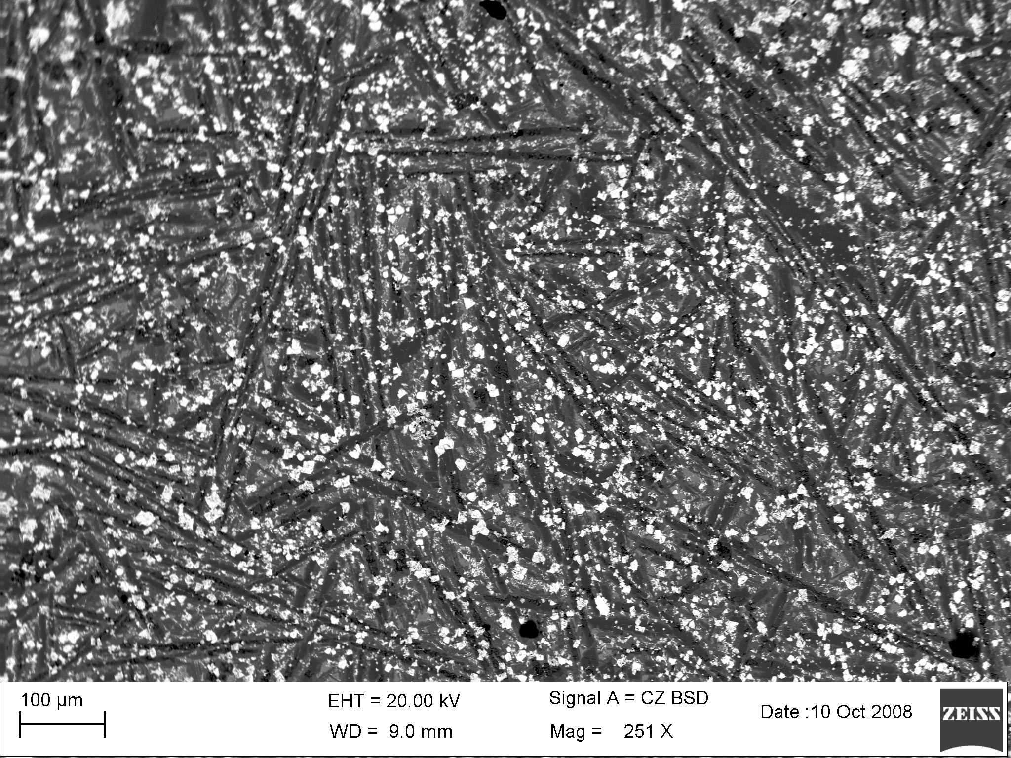
T172 162 Ptopm 250 micro
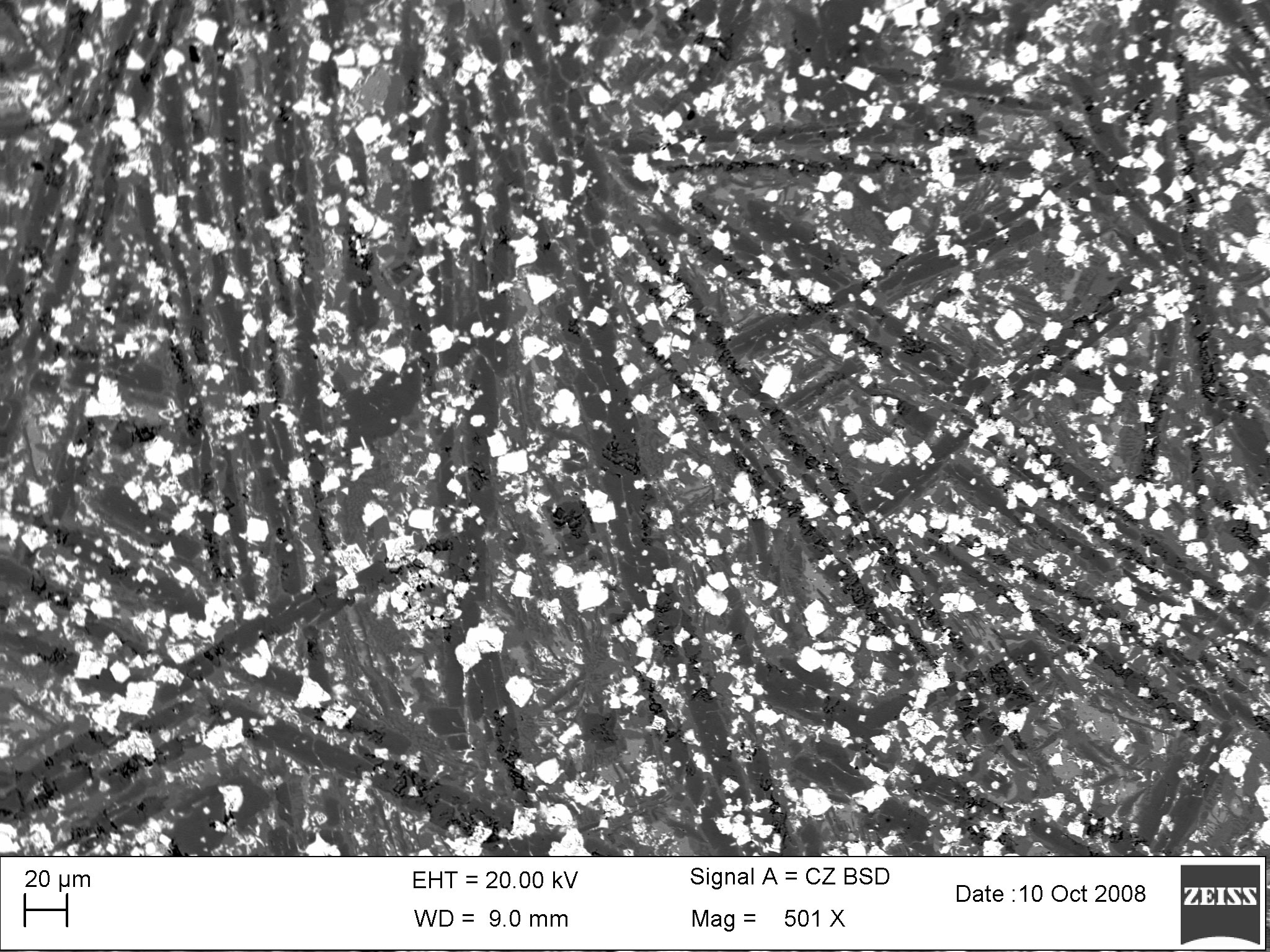
T172 162 Ptopm 500 micro
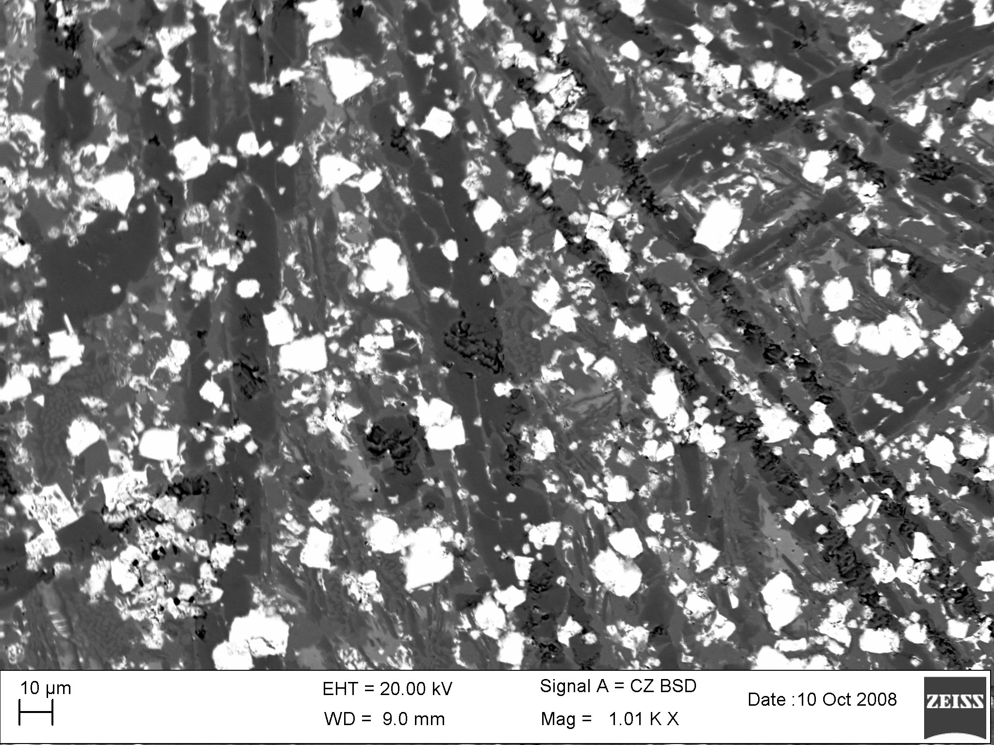
T172 162 Ptopm 1000 micro
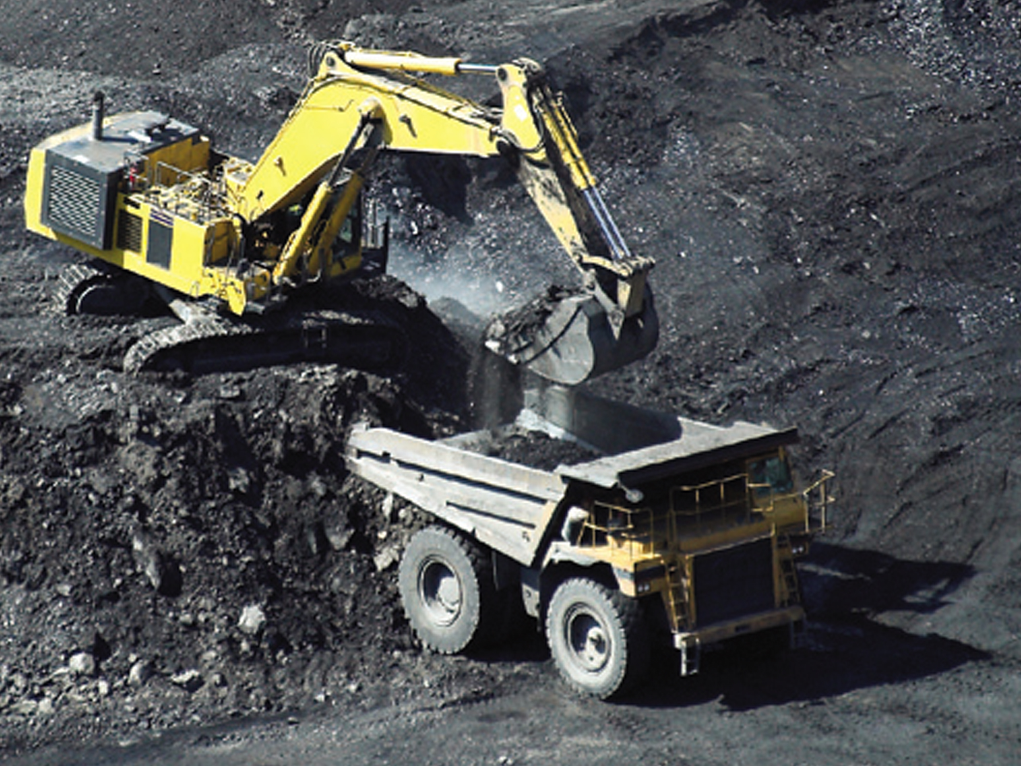
Industrial Uses - Mining
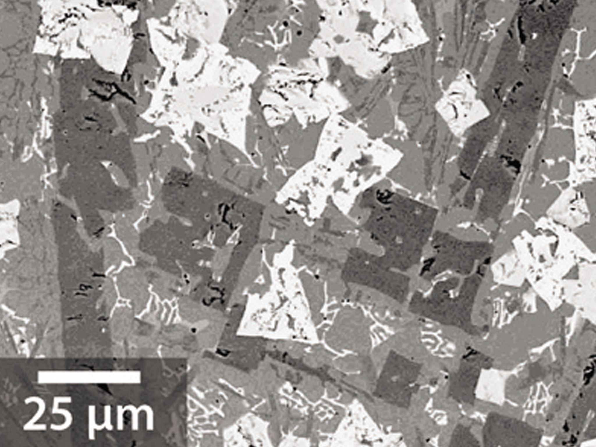
Structure 25nm - Near nanoscale (400 nm length scale) GMAW microstructure.
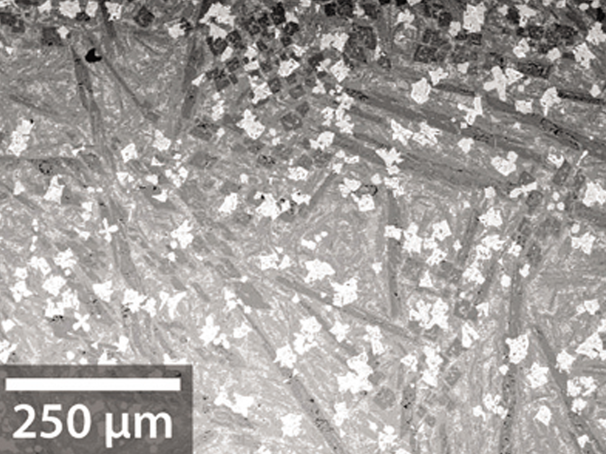
Structure 250nm - Near nanoscale (400 nm length scale) GMAW microstructure.
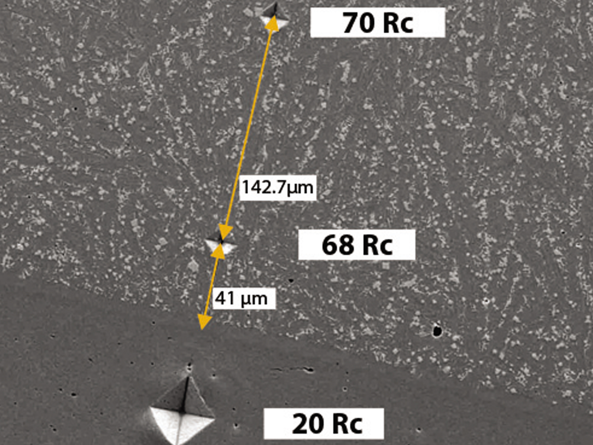
HRc Hardness - Properties are consistent throughout the entire layer.
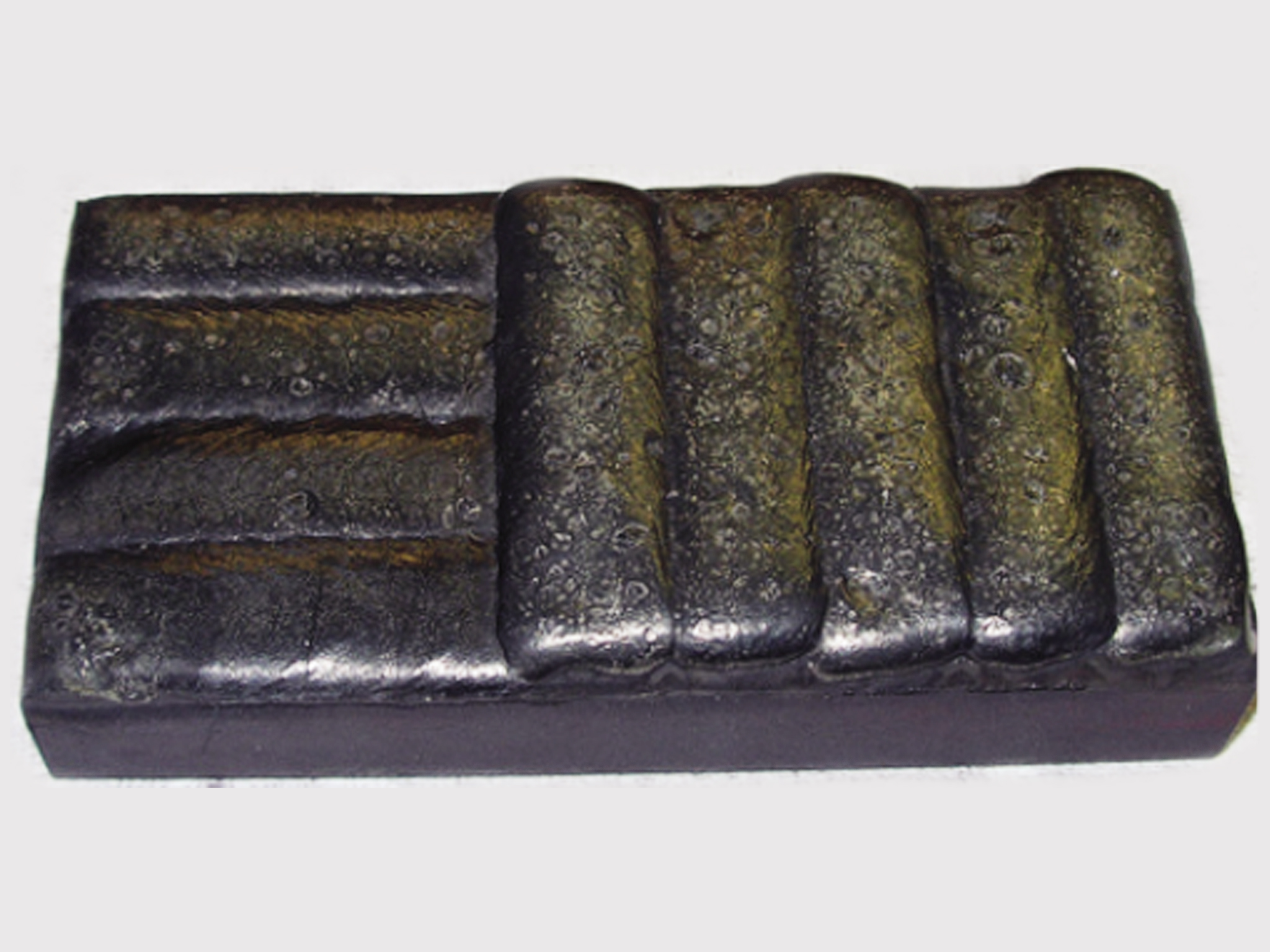
Multiple Pass Welds - T172 can be built up to a thickness of up to 0.5 in.
Hardness After Heat Treatment
SHS Single Pass Temper Curves
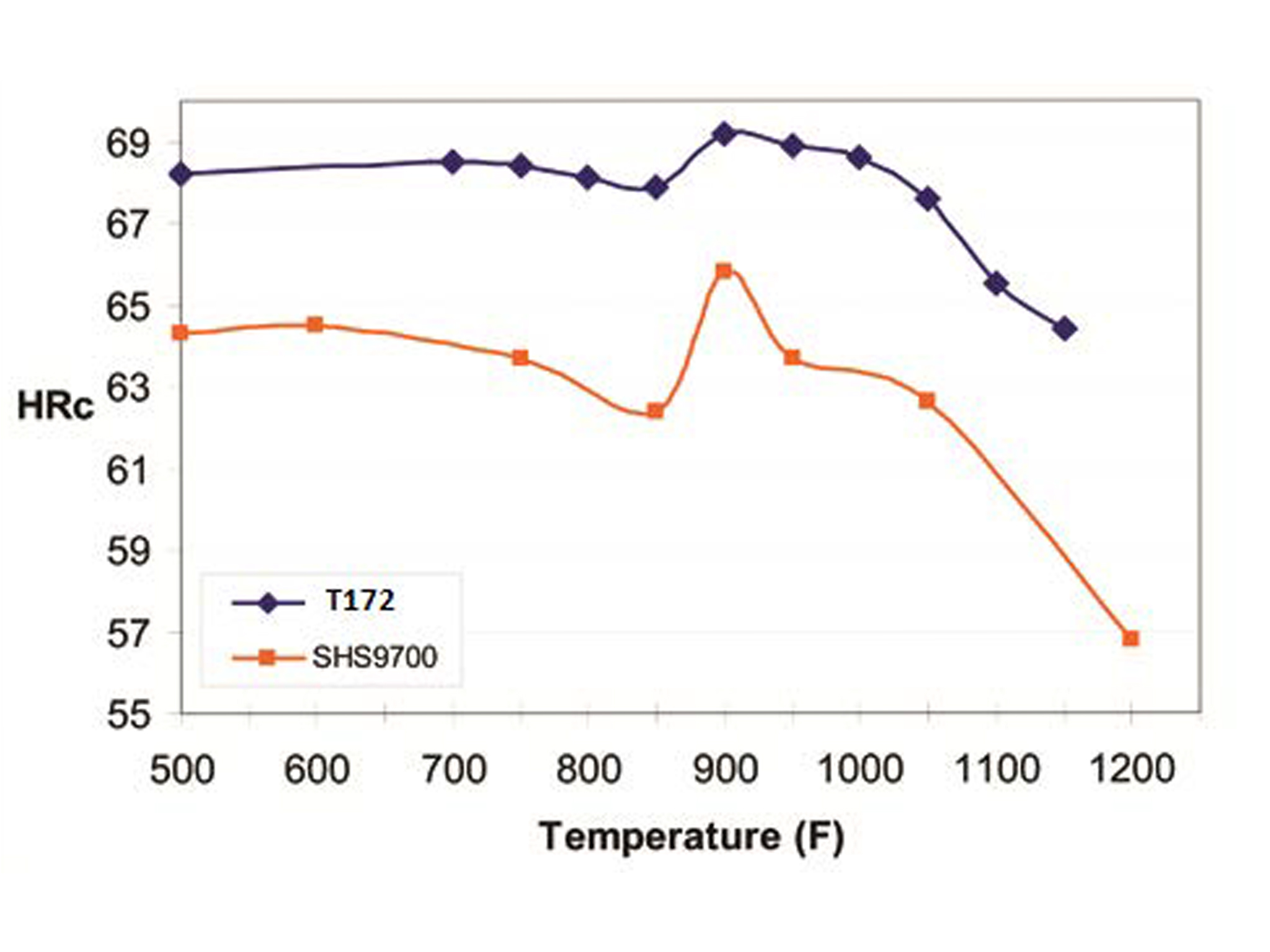
Hardness After Heat Treatment