Introduction
In standardized ASTM G65 procedure A abrasion testing, a weld overlay with macro hardness of 46–50 HRC had a lower volume loss than one with a macro hardness of 68–71 HRC. The softer plate outperformed the harder plate by a wide margin. Hardness alone does not predict wear life. Wear performance is governed by microstructure, meaning the size, distribution, and matrix support of hard phases, matched to the specific mechanism acting on the component. In coal-fired plants, five mechanisms operate: impact, abrasion, sliding, erosion, and corrosion, frequently in combination on the same part.
For maintenance engineers in coal-fired power plants, wear is a familiar and persistent problem.
Chutes, pulverizers, crushers, transfer points, ash-handling equipment, pipe elbows and other material-handling components operate in some of the most aggressive wear environments in an industrial facility. Hard mineral particles, high material velocities, impact, sliding contact, particle erosion, and elevated temperatures gradually remove material from critical surfaces.
The result is more than a worn component. Unexpected wear can mean additional inspections, unplanned maintenance, difficult repairs, replacement parts, welding and fabrication work, and outages. A component that lasts eighteen months in a plant on a twenty-four-month outage cycle is not an eighteen-month component — it is a forced outage. And when a replacement wears out sooner than expected, the maintenance team finds itself solving the same problem again, often with the same material that failed the first time.
The common response is to look for harder material. But hardness is only part of the equation, and the test data shows how small a part it can be.
Wear Is Not One Problem, It’s Several
“Abrasive wear” is often used as a catch-all term, but in a coal-fired plant it describes five distinct mechanisms, frequently acting together on the same component:
- Impact wear occurs when lumps or large particles strike a surface with force, as at chute drop points, crusher inlets, and pulverizer components. It produces localized deformation, cracking, and spalling rather than gradual thinning.
- Abrasion wear (cutting/gouging) occurs when hard mineral particles, such as silica, quartz, and other constituents in coal and ash cut or plow across a surface as material moves through chutes, liners, and transfer points.
- Sliding wear occurs when two loaded surfaces move directly against one another with little or no particle interface, producing burnishing, galling, and metal transfer. It is common on pulverizer grinding rolls and tables, crusher wear parts, and conveyor components.
- Erosion wear occurs when particles carried in a gas or fluid stream strike a surface at velocity and a shallow angle, as in cyclone separators, ash piping elbows, and pneumatic conveying lines, progressively thinning walls.
- Corrosion (corrosive wear) occurs when chemical attacks from moisture, sulfur compounds, or elevated temperatures accelerate material loss alongside the mechanical mechanisms above, particularly in ash-handling systems.
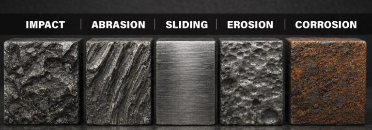
These mechanisms leave different signatures, and the worn surface itself is the most reliable evidence available. Deep craters and chipped edges indicate impact. Coarse directional furrows indicate gouging abrasion. A polished, burnished surface with fine directional lines indicates sliding. Rippled or scalloped thinning, often on the outside radius of an elbow, indicates particle erosion. Pitting and scale beneath the wear surface indicates corrosion compounding mechanical loss.
Two components with the same visible symptom, a thinned liner or a holed elbow, may be failing for different reasons. Selecting harder material may solve one of these problems while doing little for another. The more useful question isn’t “what’s the hardest material available?” It’s “what is actually causing this component to wear, and what material structure resists that specific mechanism?”
That question is where metallurgy becomes a practical maintenance tool rather than an academic exercise.
Why Hardness Alone Doesn’t Predict Wear Life
Bulk hardness measures a material’s average resistance to indentation. Wear resistance depends on what happens at the scale of individual abrasive particles: whether a particle can cut the surface, whether hard phases are coarse enough to obstruct it, and whether the surrounding matrix holds those phases in place under load.
These are not the same property. The four weld overlays below were tested under ASTM G65-04 Procedure A, 6,000 cycles — the standard dry sand/rubber wheel abrasion test:
Overlay | Hardness (HRC) | G65 mass loss |
Chromium carbide (T Plate) | 54–60 | 0.20 g (±0.03) |
Complex carbide (T161) | 60–62 | 0.11 g (±0.03) |
Submicron carbide (T168i, T171) | 68–71 | 0.08 g (±0.02) |
Nickel matrix, tungsten carbide (T170) | 46–50 | 0.05 g (±0.03) |
The softest overlay tested had the lowest mass loss.
The softest overlay on the list has the lowest mass loss. It sits more than twenty Rockwell points below the hardest material and still outperforms it in abrasion.
The explanation is microstructural. That overlay carries macrocrystalline tungsten carbide particles in a nickel-chrome-iron matrix. Because the carbides do not degrade during the welding process, the finished surface retains ductility and absorbs impact rather than fracturing. A single bulk HRC reading averages the very hard carbide together with the softer matrix supporting it and that average conceals the structure actually doing the work.
The practical consequence for a maintenance organization is direct: a purchase specification written around a minimum hardness number can screen out the material that would have performed best in the application.
What the ASTM G65 Test Does and Doesn’t Measure
ASTM G65 is the reference point most wear plate specifications cite. Silica sand is fed between a rotating rubber wheel and a test coupon under fixed load, and the coupon’s mass loss is recorded prior and post test. Lower mass loss indicates better performance. It is repeatable, standardized, and genuinely useful.
It is also a test of one mechanism. G65 measures low-stress three-body abrasion and is a static test. It does not take into account impact resistance, sliding wear, high-temperature performance, or corrosive attack. A plate with excellent G65 figures can still fail early under repeated impact loading, and a plate with mid-range G65 figures can substantially outlast it in a high-impact chute.
Where impact is present, abrasion data should be paired with drop impact testing or a toughness benchmark. Where temperature is a factor, hot hardness data matters more than room-temperature hardness, as many overlays soften well below the temperatures found in ash-handling and boiler-adjacent service. Reading a single G65 number as a proxy for service life repeats the hardness error one level further down.
What a Metallurgical Failure Analysis Actually Involves
A worn or failed component contains real diagnostic information, and reading it is a specific discipline. Trimay’s materials engineers and metallurgists, including PhD-level specialists, approach a wear failure the way a forensic investigator approaches a scene: gather physical evidence first, then analyze and conclude cause.
That process typically includes:
- Visual and macroscopic examination of the wear pattern, its shape, location, and distribution, to narrow down which mechanism or combination is responsible.
- Microstructural analysis, often using scanning electron microscopy (SEM) and optical metallography, to examine how the material’s internal phases and grain structure responded to service.
- Chemistry verification, confirming the alloy composition matches what the application requires and identifying any degradation, decarburization, or unexpected phase changes.
- Hardness mapping across the cross-section, not just a single surface reading, since material can be hard at the surface and behave very differently a few millimeters in.
Cross-sectional mapping matters more than it may appear. Many overlays lose hardness as they approach the weld interface, which means the effective protective life of the plate is shorter than its nominal thickness suggests. A plate specified at 8 mm may deliver considerably less than 8 mm of usable wear surface. Verifying hardness through the full deposit is the difference between a stated thickness and a protective one.
This distinction matters because two materials can carry similar bulk hardness ratings on a spec sheet while performing very differently in service. A wear-resistant alloy typically contains very hard phases (carbides or borides) that resist abrasive particles, supported by a tougher surrounding matrix that resists cracking and fracture under impact. The goal isn’t to make the entire material as hard as possible; it’s to balance hardness, toughness, and microstructure for the specific mechanism identified in the field.
From Analysis to Application-Specific Solution
For a maintenance engineer, metallurgy only matters if it produces a usable answer. The process starts with the application itself:
What material is being handled, and what is its mineral content? What are the particle characteristics and velocities? Is the dominant mechanism impact, cutting abrasion, sliding, or particle erosion? What temperatures and moisture levels are present? How frequently is the component currently being inspected or replaced, and what does that pattern suggest about the mechanism at work?
These answers shape the material response. Depending on the findings, the solution may involve a different base alloy, a weld-overlay or hardfacing plate, a change in wear-surface thickness or configuration, or a redesign of the component itself.
This is one reason weld-overlay technology, also referred to as hardfacing, has become a central tool for extending service life on chute liners, transfer points, and other high-wear surfaces. Rather than relying only on a conventional base material, an engineered overlay introduces a wear-resistant surface designed specifically for the conditions that surface will encounter.
Microstructure: The System Behind the Number
Think of a wear-resistant material as an engineered system, not a single hardness reading. Alloy chemistry determines which phases can form. Processing determines the resulting microstructure. Microstructure determines how the material responds to abrasive particles, impact, and mechanical load.
For severe-abrasion service, one established approach is to distribute hard carbide or boride phases within a tougher metallic matrix: the hard phases resist the abrasive particles directly, while the matrix provides support and helps the material tolerate the mechanical stresses of service.
The mechanism by which this works is specific. In a refined borocarbide overlay, glass-forming chemistry permits high undercooling during welding, driving the crystalline microstructure into the near-nanoscale (submicron) range. The resulting borocarbide phases are fully wetted by a ductile ferrite matrix, which prevents premature carbide pull-out, delamination, and crack nucleation. The refined phase size reduces stress concentration sites, while the ductile matrix supplies crack blunting and bridging. The result is a material that delivers 0.08 g G65 mass loss alongside toughness equivalent to 400 Brinell quenched-and-tempered plate, two properties normally traded against one another.
The underlying principle extends beyond any single formulation: wear performance is determined by structure and properties working together, not by hardness in isolation.
Why This Matters Specifically in Coal-Fired Power Generation
Coal, ash, and other bulk solids handled in a coal-fired plant contain mineral constituents that are inherently abrasive, and equipment across the plant experiences different combinations of these mechanisms depending on where it sits in the process.
Pulverizing equipment is one example, where sliding wear and impact both act on grinding components — a combination that penalizes materials selected purely for abrasion resistance, since the hardest available surface is often the most prone to chipping under repeated impact. Chutes and transfer points are another, where high-velocity material flow drives cutting abrasion. Classifier cones, fuel transfer piping, and fan scroll liners see particle erosion, where stream angle and velocity determine where walls thin first, and where a flow-path change sometimes outperforms a material change. Ash-handling systems add corrosive wear to the mix, where moisture and chemical exposure compound mechanical material loss, often at elevated temperature.
Relatively small differences in wear rate compound into meaningful differences in maintenance intervals over years of continuous operation.
A part that lasts 18 months in a plant on a 24-month outage cycle isn’t an 18-month part. It’s a forced outage.
For these applications, extending wear life isn’t just about a component lasting longer in isolation. It changes the maintenance equation. A wear component that survives longer gives maintenance teams more flexibility to schedule inspections and repairs around planned outages rather than reacting to premature failure. Fewer replacements also reduce downstream welding, fabrication, and labor demands.
The economic value of a wear-resistant material comes from its total maintenance impact over the life of the equipment, not the purchase price of the plate.
A Different Way to Frame the Problem
For maintenance organizations, the more useful shift is moving away from treating wear as an unavoidable replacement cycle.

Not every wear problem requires a full metallurgical investigation. But when a component is wearing faster than expected, or repeated replacement has quietly become part of the routine, it’s worth asking whether the underlying mechanism is understood or just assumed.
Sometimes the answer is a different alloy. Sometimes it’s a different overlay. Sometimes it’s a change to component design or operating conditions. And sometimes the existing material is correct, but the installation or application needs adjustment. Metallurgical analysis is what connects a symptom to the right one of these answers, rather than defaulting to “try something harder.”
Turning Materials Science into Maintenance Value
At Trimay — a UCC Environmental company — wear technology brings PhD-level metallurgical expertise together with UCC’s operating experience in the power-generation and industrial markets. That expertise includes specialists such as Jason Li, PhD, who holds a doctorate in Materials and Welding Engineering from the University of Alberta and has published peer-reviewed research on hardfacing overlays reinforced with micro- and nano-scale borides. The combination treats high-wear components as engineering problems to be diagnosed, not just parts to be replaced on a schedule.
Because when a component wears out, the immediate question is how quickly it can be replaced. The more useful question, the one that actually changes outcomes, is why it wore in the first place, and whether the next solution can be engineered to outlast it.
That is where metallurgy moves from the laboratory into the plant: turning an understanding of material behavior into a practical, measurable improvement in wear life.
Contact us to connect with our experts to find the right wear solutions for your application.
Overlay performance figures cited above are from published Trimay datasheets, tested under ASTM G65-04 Procedure A, 6,000 cycles.